Heltec T096
A GNSS-backed reference clock with physical timestamps for both BLE transmission and reception. One platform can serve as a grandmaster, a hot standby or a relay clock.
Protocol features
These firmware profiles use the same hardware in different clock roles.
- GrandmasterIndependent GNSS / PPS source
- Originates the network time reference from its own GNSS time and PPS. Eligible, authorized clocks participate in automatic source selection.
- Hot standbySynchronized, eligible and admitted
- Follows the serving grandmaster while preparing to take over. HOT requires synchronized time, independent source eligibility and current permission.
- Relay clockBoundary-clock profile
- Disciplines its own clock from an authenticated parent and originates a separate downstream timing train, preserving the original root and inherited source age.
A relay preserves its upstream reference; it does not gain independent grandmaster authority. Role support and the measured precision of a specific path are separate capabilities.
Recognizing the clock’s state
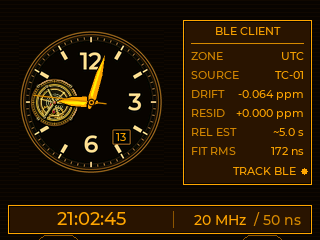
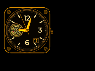
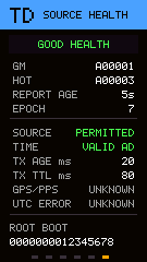
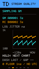
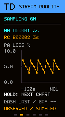
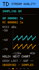
The firmware display keeps source, role and synchronization state visible. The analog dial appears in the locked GM and HOT previews; GPS acquisition uses the status panel.
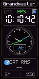
Grandmaster · locked
The serving GPS reference shows the analog dial and GM state.
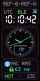
HOT standby · locked
The standby keeps a synchronized dial while following the serving grandmaster.
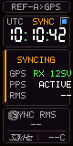
GPS synchronization
The acquisition panel remains visible while the GPS reference is settling.
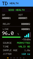
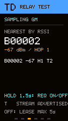
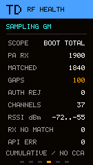
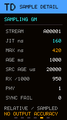
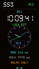
Firmware UI previews rendered from the repository at the display’s native 80 × 160 pixels, using illustrative state inputs. They are not photographs or live lock observations.
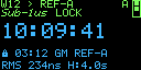
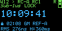
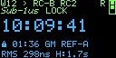
Additional relay screen previews
Candidate illustrations for relay profiles and acquisition states.
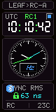
Following RC1
A downstream clock follows one relay hop and shows the RC1 source marker.
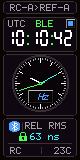
Relay clock operation
The RC profile shows its disciplined local time while serving downstream.
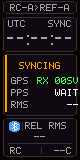
Relay acquisition
The relay is acquiring its parent; an analog lock is not displayed yet.
Hardware specifications
The CPU cycle, timestamp tick and PPS accuracy describe different parts of the clock.
| Specification | Value & timing relevance |
|---|---|
| MCU | Nordic nRF52840 Arm Cortex-M4F Source |
| CPU clock / cycle | 64 MHz / 15.625 nsSource |
| Timestamp timer / tick | 16 MHz / 62.5 ns Hardware capture and compare; 32-bit counter. Source |
| Memory | 1 MB flash · 256 KB RAMSource |
| Specification | Value & timing relevance |
|---|---|
| BLE radio | 2.4 GHz · Bluetooth LE 1M, 2M and LE Coded PHY capability; measured precision profile uses BLE 1M. Source |
| BLE TX timestamp | Hardware event capture RADIO ADDRESS event → PPI → TIMER capture. Source |
| BLE RX timestamp | Hardware event capture RADIO ADDRESS event → PPI → TIMER capture; receive reference delay requires calibration. Source |
| Event capture path | Peripheral-to-peripheral PPI latches the counter without waiting for a software callback. Source |
| Specification | Value & timing relevance |
|---|---|
| Onboard receiver | Unicore UC6580 · L1 + L5Source |
| PPS timing accuracy | 20 ns RMS Manufacturer family specification; see reference notes below. Source |
| PPS capture | GPIO event → PPI → TIMER Uses the same 16 MHz counter as the BLE timestamps. Source |
| Source discipline | GNSS time + physical PPS A fresh fix, pulse and valid time association establish the reference. Source |
| Specification | Value & timing relevance |
|---|---|
| Display | 0.96-inch colour TFT · 80 × 160Source |
| Power | USB-C 5 V · lithium batterySource |
| Board dimensions | 52 × 25.4 × 10.26 mmSource |
| Other onboard radio | SX1262 LoRa PToB precision results on this page use BLE. Source |
Understanding the 20 ns PPS specification
Unicore’s UC6580 family brochure lists 20 ns RMS time accuracy. This describes PPS timing accuracy, rather than free-running oscillator drift or the total error of a BLE clock.
The UC6580x-00 R1.7 datasheet lists 5 ns RMS. Match the chip variant, receiver settings and measurement conditions before using either figure in an accuracy budget. Antenna, electrical and capture delays also contribute. The research paper documents these reference specifications.
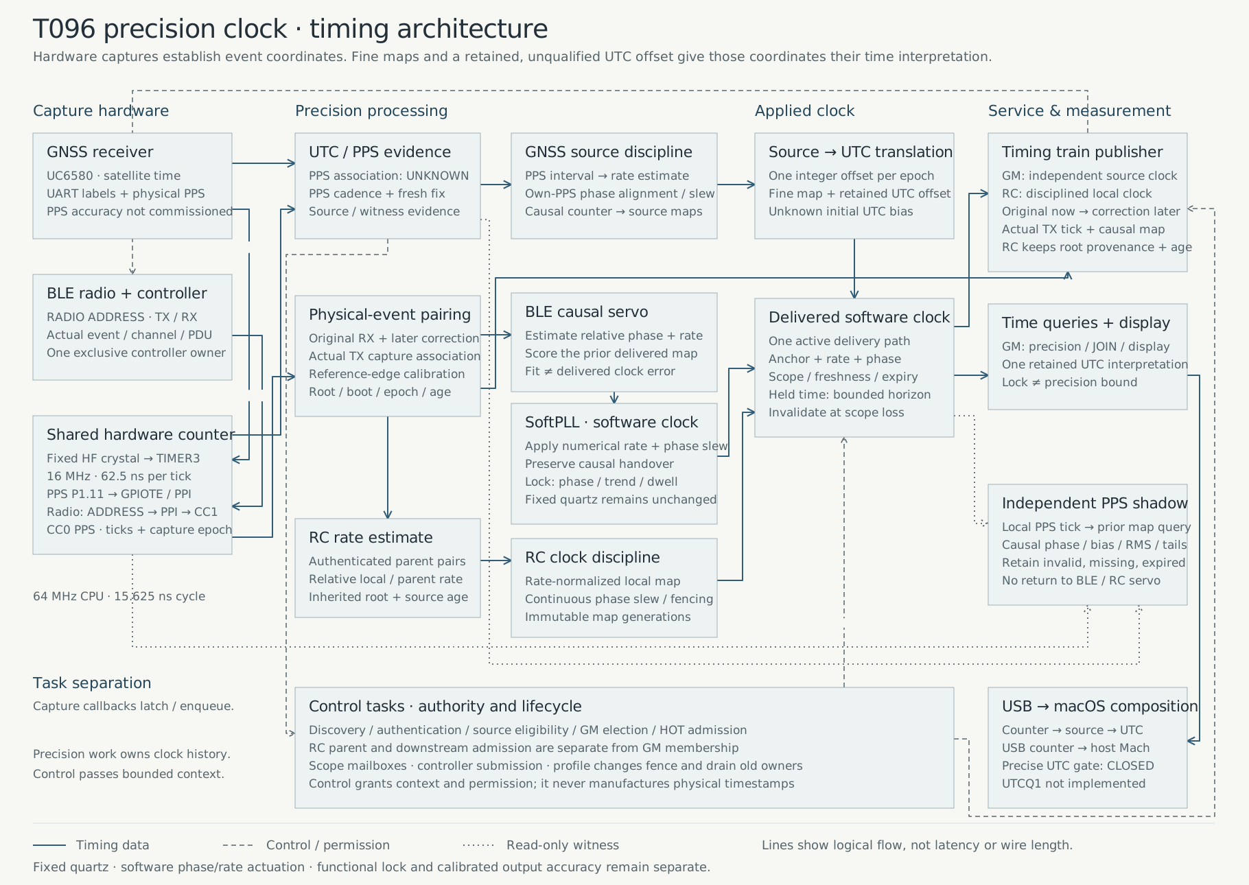
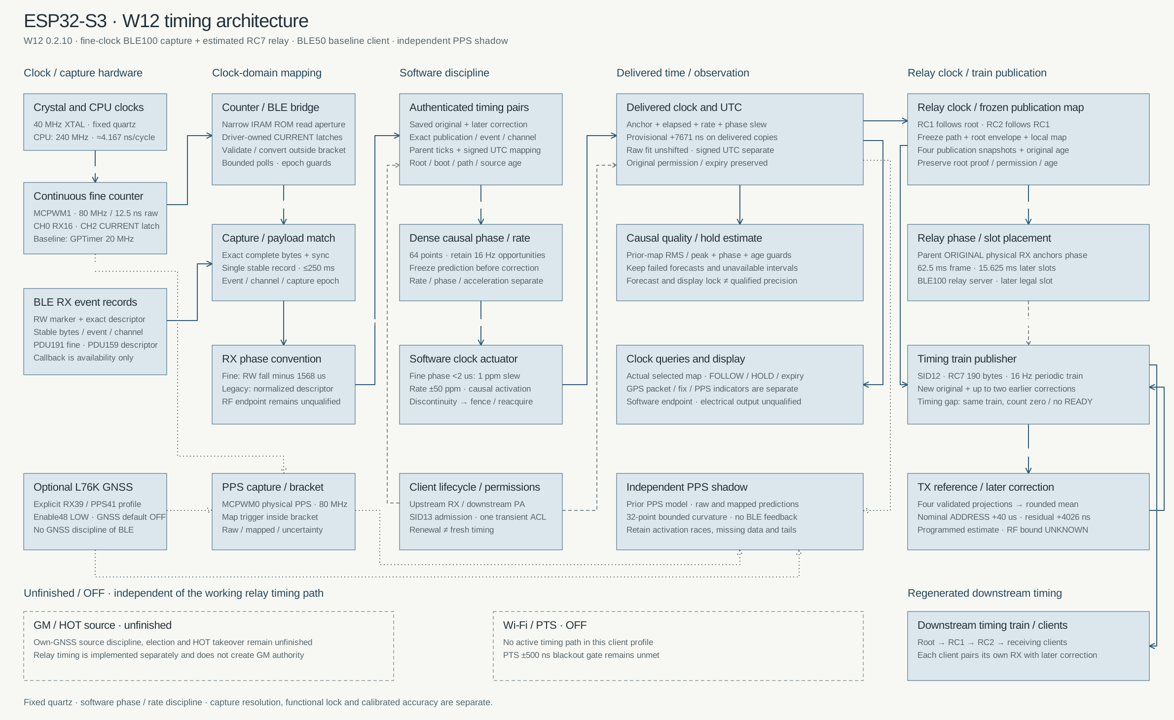
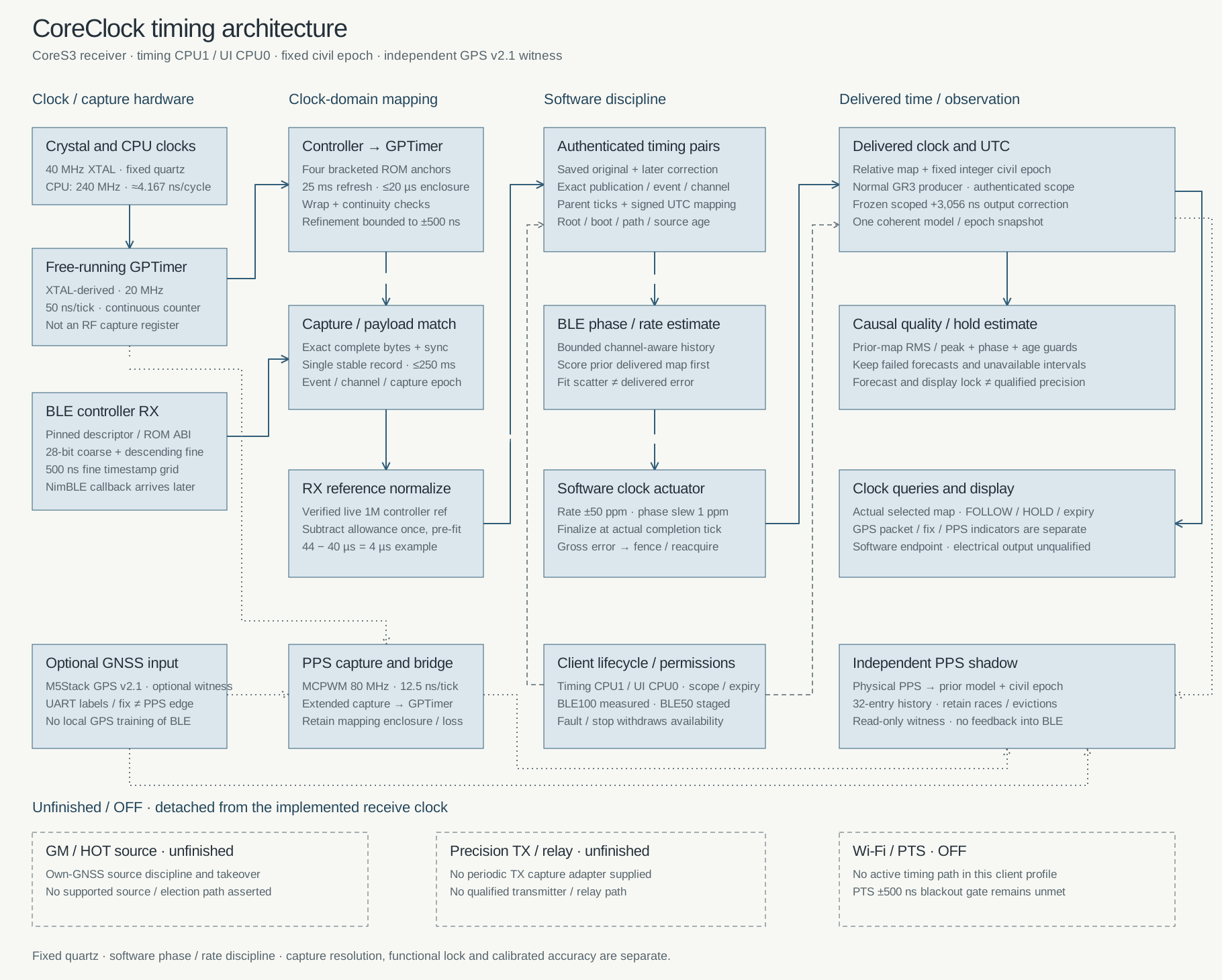
T096 timing architecture
Follow hardware capture through the servo, SoftPLL and delivered clock. Explore each mode and trace drift or offsets.
Open the interactive schematicFrom physical event to shared time
BLE TX, BLE RX and GPS PPS edges can be captured against the same local counter. Follow-up timing identifies the actual transmit event; the receiver uses those observations to discipline its clock.
A 15.625 ns CPU cycle helps execute the estimator. A 62.5 ns timer tick determines the capture grid. Neither number alone is an end-to-end accuracy guarantee.
A reference for sub-microsecond timing
The T096 provides the hardware capture and GNSS reference needed to build a precision timing network. The V14 research paper measured a grandmaster → relay clock → receiver path against an independent local PPS witness.
| Statistic | Result |
|---|---|
| RMS, including bias | 62.504 ns |
| 95th-percentile absolute error | 123.25 ns |
| 99th-percentile / maximum | 160.25 / 191 ns |
| Usable / nominal observations | 436 / 602 72.425% |
These results measure fractional-second phase in the usable PPS-shadow population over approximately 602 seconds. Missing reference edges and expired maps remain in the coverage count. Calibrated electrical output and absolute UTC accuracy need their own measurements.
For a sub-100 ns absolute-error limit on 95% of observations, validate the complete timing path against that percentile. The measured 62.504 ns RMS and 123.25 ns P95 describe different performance criteria.
Read the measured resultsSource references
- T096 firmware · GitHub README
- Heltec T096 board specification
- Nordic nRF52840 product specification
- Nordic TIMER capture and compare
- Nordic PPI event interconnect
- Unicore UC6580 · 2026 brochure, p. 28
- Unicore UC6580x-00 · R1.7 datasheet, p. 7
- PToB V14 research paper